As nerdy as this sounds, don't let rocket science overwhelm you. In fact, I had the immense displeasure in complicating our rocket design to my mom and dad. But after 2 months of making it simpler and digestible for my amateur parents I can say that with an intermediate understanding of physics and mathematics these steps are sufficient for you to deisgn a pintle injector and launch your rocket to Mars. (PS: just kidding, baby steps!)
If you are wondering what a pintle injector is. Every rocket engine must have an instrument to inject the fuel and oxidiser in a chamber with certain speeds and ratios to combust and generate thrust. A pintle injector is that instrument which helps accomplish this function.
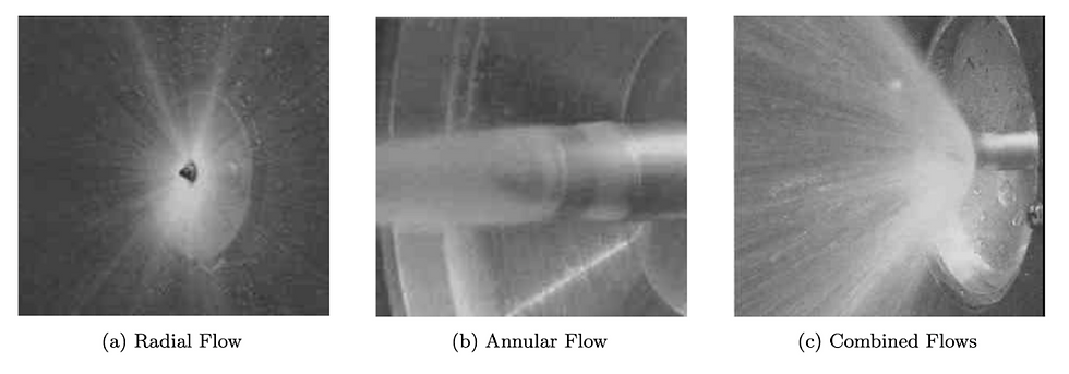
Visualizing fuel and oxidiser flow (Lee et al.)
As seen in the image above, the radial flow of the Liquid Oxygen (LOx) and the annular flow of the Jet-A fuel collide and produce a flow which is directed by a vector sum of both the flows. This is called the spray angle which is significant for us and must be around 60 degrees after reviewing literature and research.
This pintle design is based on this spray angle which is parameterized by the local momentum ratio (LMR) given by
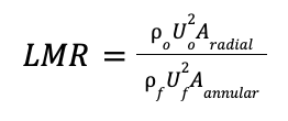
Where,
p is density, U is injection velocity and A is discharge area
o represents the LOx flow and f represents the fuel flow
Furthermore, the spray angle is given as a function of LMR
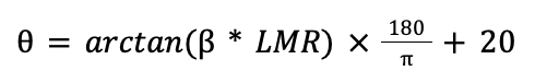
Where,
B is a plotting constant
To make this more simple to understand we can manipulate the A(radial) and A(annular) to produce an effective spray angle. In fact, a fast way to do this is writing a python script to automate iterations to find A(radial) and A(annular) given by the formula below
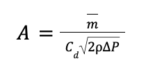
Where,
m is the mass flow rate, C(d) is the discharge coefficient, p is the density of fuel/LOx and P is the pressure drop
It is amazing how everything is intertwined, but this amazement can be very frustrating when we start changing various factors together which creates a 10 variable problem which innumerable solutions for different optimisations. From our experience it is worth changing the pressure drop P and the type of fuel or oxidiser used which will change the density .
Finally, after figuring out a good fuel-oxidiser configuration for a reasonable pressure drop and a needed mass flow to achieve a significant altitude it is time to transpose the numbers to sizes for our pintle design.
For a radial oxidiser flow the discharge area must be divided between the orifice openings where the number of equally distant orifices is given by the Aradial/r2. For the annular flow the discharge area must be divided by the area between two concentric circles which create the gap given by Aannular/(R2-r2).
With the help of the annular gap size and radius of the orifices we have designed the most essential aspects of the pintle injector which affect the spray angle directly. However, there are other structural factors which must be accounted for when designing the injector body as a whole. This becomes a study which must involve the internal flow geometry of the fuel and oxidiser and can be explained better in a future blog. For now, run-fail-reiterate your way to designing your very own pintle injector!
Comments