
To test liquid rocket engines, we’re building a test stand. On the electrical system of the test stand, we’re also doing a lot of testing within. We’ve built two solenoid test circuits to toggle AC and DC solenoids, and are now in the second iteration of the DAQ testbed, a board with the bare minimums to try out chips and sensors we have never used before. The first testbed only had a few test points for our probes, so this second one has even more. There’s also the interface board, designed for the purpose of testing the other boards independently from the other systems.
Here on electrical, everything is built to be tested, and we plan for it by following a very modular architecture. Here's what we have so far:
The plan and its progress
The primary requirements of the electrical system include valve actuation, data collection, and fail-safe modes. To accomplish these, we created an architecture revolving around a Data Acquisition Unit (DAQ), Control & Command Unit (C&C), Actuation Board, Test Stand Computer, and a remote Bunker Computer.
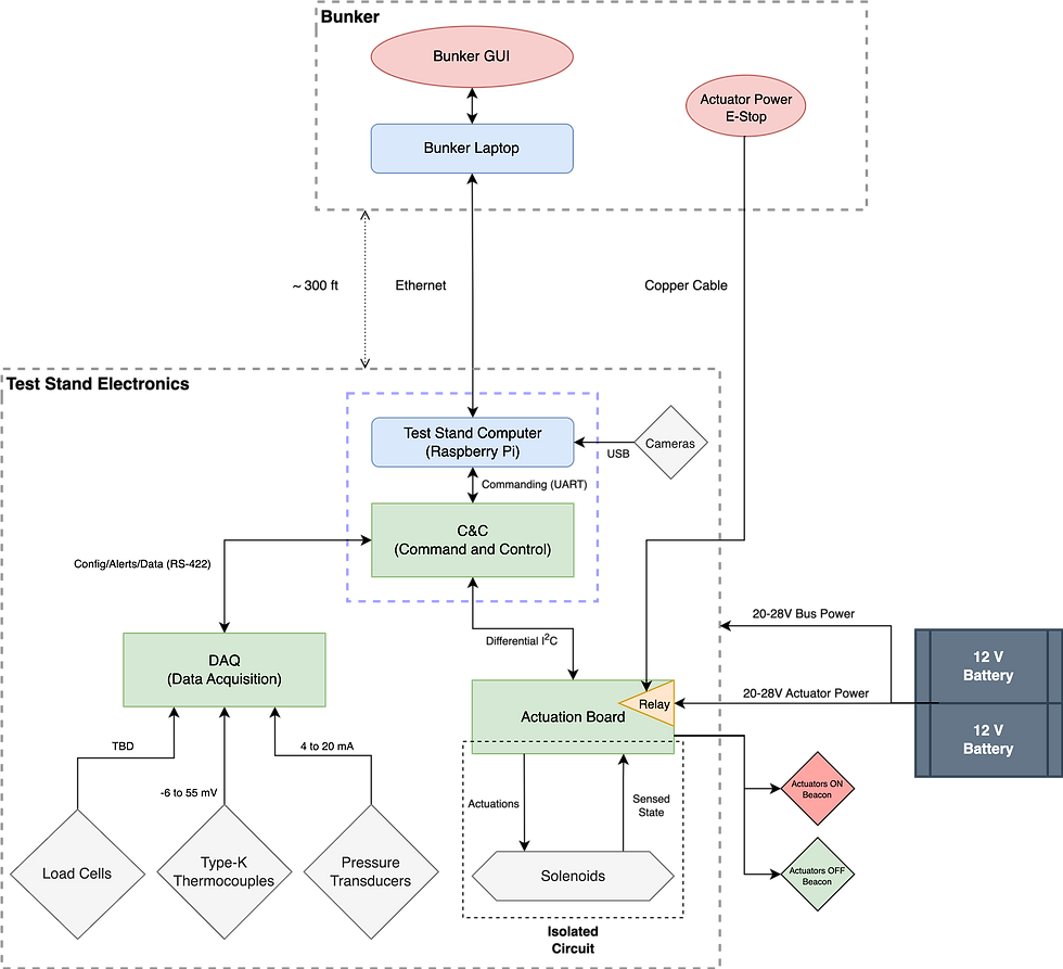
DAQ

This unit collects data of the engine temperatures, valve pressures, and thrust output. It contains Analog to Digital Converter (ADC) chips to decode the analog sensor data into measurement values in their respective units that can be sent to the bunker computer.
So far, we’ve finished assembly of the second version of the DAQ testbed, a custom printed circuit board (PCB) designed by the team to test and develop firmware for SPI communication with ADCs, and experimented with reading sensor data on a smaller scale to identify mistakes and iterate with low costs. After the first DAQ Testbed, we gained useful experience about debugging, PCB best practices, and the components that would be useful for the final DAQ. With the three new Testbed v2 boards, we can move fast in developing firmware and stress testing in parallel.
Command and Control (C&C)

This unit collects digital sensor data from DAQ, generates commands to the actuation board, and puts the stand in a fail-safe mode based on sensor data or human input.
We just finished designing the interface board, which will make an off-the-shelf STM32 development board act as the C&C for now. If this works well, we’ll design the full C&C to integrate the microcontroller.
Actuation Board

This unit manages the high power to actuate solenoids. To test the solid state relays we plan to use on this board, we wired up a small circuit to toggle one of the solenoids that have arrived. With a function generator, we were able to switch compressed air on and off at more than thirty times a second! In the process, we learned how to use flyback diodes to protect our circuitry driving inductive loads, and we can now move forward with the full actuation board schematic.
STM32 Training
We're all continuously learning. New members received STM32F303RE (Nucleo-64) development boards to learn the C programming language within the STM32 environment, I2C/SPI communication protocols, and manipulating the registers in various sensors. Both the C&C and the DAQ will have STM32 microcontrollers.
An emphasis on modularity
The DAQ can be operated on its own, without the rest of the test stand. We can also control the DAQ or actuation board individually without the full C&C. This allows us as a team to debug multiple subsystems in parallel, and learn about our equipment and sensors before we put them on the stand. Additionally, this allows for changing sensor or actuator requirements. For example, one load cell may require 10V and output a 4mA signal at minimum force, varying to 20mA at maximum force. Another may require 24V and output a signal between 0 and 5V. This being a test stand, we may want to try different configurations for different engines or collect data that we didn’t anticipate needing. For such a dynamic project, we want the option of redesigning a single board in the case we need to switch out hardware, instead of spending much more time, effort, and money redesigning the entire system.
Modularity also means that we can worry less about one subsystem propagating an error to another subsystem in the case it malfunctions. The DAQ and C&C each have their own power lines straight from the battery, and will have their own protection circuitry against overvoltage and reverse voltage. Earlier, we had planned for the C&C to take in the battery power, step it down to the correct voltages, then distribute to the others, but we decided against it because then the DAQ would have to rely on the C&C’s power being undisturbed. Plus, there would be a lot of current flowing through the connection. If for some reason the 5V gets shorted to 24V on one board, killing all of the 5V circuits on that board, the other boards won’t be affected because the 5V are local to each board. For more safety, we follow strict electrical isolation on the actuation board between circuitry that interacts with the solenoids and the circuitry that communicates with the rest of the board. If a solenoid malfunctions, its high power won’t have influence on the rest of the system—there is a line on the board over which no electrical currents can pass: signals are transmitted across this gap with optics.
With versatility and protection built into the system, we hope that the test stand electronics can grow with the Liquid Rocket Initiative as our goals become increasingly ambitious. This semester the electrical team created a solid plan and gained plenty of experience with prototypes, and we hope that we can get these boards interfacing with more hardware soon!
Comments